2 Optimization in VR
2.1 Basics of Optimization
Volume rendering can produce informative images that can be useful in data analysis, but a major drawback of the techniques is the time required to generate a high-quality image. Several volume rendering optimizations are developed which decrease rendering times, and therefore increase interactivity and productivity It is obvious that one can not hope to have a real time volume rending in the near future without investing time, effort, and ingenuity in accelerating the process through software optimizations and hardware implementations. There are five main approaches to overcoming this seemingly insurmountable performance barrier:
1. Data reduction by means of model extraction or data simplification,
2. Software-based algorithm optimization and acceleration,
3. Implementation on general-purpose parallel architectures,
4. Use of contemporary off-the-shelf graphics hardware, and
5. Realization of special-purpose volume rendering engines.
2.2 Task and data decomposition
Since the work is essentially defined as “operations on data”, the choice of task decomposition has a direct impact on data access patterns. On distributed memory architectures, where remote memory references are usually much more expensive than local memory references, the issues of task decomposition and data distribution are inseparable. Shared memory systems offer more flexibility, since all processors have an equal access to the data. While data locality is still important in achieving good caching performance, the penalties for global memory references tend to be less severe, and static assignment of data to processors is not generally required.
There are two main strategies for task decomposition. In an object-parallel approach, tasks are formed by partitioning either the geometric description of the scene or the associated object space. Rendering operations are then applied in parallel to subsets of the geometric data, producing pixel values which must then be integrated into a final image. In contrast, image-parallel algorithms reverse this mapping. Tasks are formed by partitioning the image space, and each task renders the geometric primitives which contribute to the pixels which it has been assigned. To achieve a better balance among the various overheads, some algorithms adopt a hybrid approach, incorporating features of both object- and image-parallel methods. These techniques partition both the object and image spaces, breaking the rendering pipeline in the middle and communicating intermediate results from object rendering tasks to image rendering tasks.
Volume rendering algorithms typically loops through the data, calculating the contribution of each volume sample to pixels on the image plane. This is a costly operation for moderate to large sized data, leading to rendering times that are non-interactive. Viewing the intermediate results in the image plane may be useful, but these partial image results are not always representatives of the final image. For the purpose of interaction, it is useful to be able to generate a lower quality image in a shorter amount of time, which is known as data simplification. For data sets with binary sample values, bits could be packed into bytes such that each byte represents a 2´2´2 portion of the data. The data would be processed bit-by-bit to generate the full resolution image, but lower resolution image could be generated by processing the data byte-by-byte. If more than four bits of the byte are set, the byte is considered to represent an element of the object, otherwise it represents the background. This will produce an image with one-half the linear resolution in approximately one eighth the time.
2.3 Software-based algorithm optimization and acceleration
Software based algorithm optimizations are divided into two broad groups according to the rendering methods they use, that is optimization methods for object-space rendering and image-space rendering. The methods that have been suggested to reduce the amount of computations needed for the transformation by exploiting the spatial coherency between voxels for object-space rendering are:
1. Recursive “divide and conquer”,
2. pre-calculated tables,
3. incremental transformation, and
4. shearing-based transforms.
The major algorithmic strategy for parallelizing volume rendering is the divide-and-conquer paradigm. The volume rendering problem can be subdivided either in data space or in image space. Data-space subdivision assigns the computation associated with particular sub volumes to processors, while image-space subdivision distributes the computation associated with particular portions of the image space. This method exploits coherency in voxel space by representing the 3D volume by an octree. A group of neighboring voxels having the same value may, under some restrictions, be grouped into a uniform cubic sub volume. This aggregate of voxels can be transformed and rendered as a uniform unit instead of processing each of its voxels.
The table-driven transformation method is based on the observation that volume transformation involves the multiplication of the matrix elements with integer values which are always in the range of volume resolution. Therefore, in a short preprocessing stage each matrix element is allocated a table. All the multiplication calculations required for the transformation matrix multiplication are stored into a look-up table. The transformation of a voxel can then be accomplished simply by accessing the look-up table, the entry accessed in the table depending on the xyz coordinates of the voxel. During the transformation stage, coordinate by matrix multiplication is replaced by table lookup.
The incremental transformation method is based on the observation that the transformation of a voxel can be incrementally computed given the transformed vector of the voxel. To employ this approach, all volume elements, including the empty ones, have to be transformed. This approach is especially attractive for vector processors since the transformations of the set of voxels can be computed from the transformation of the vector by adding, to each element in this vector. Another method exploits coherency within the volume to implement a novel incremental transformation scheme. A seed voxel is first transformed using the normal matrix-vector multiplication. All other voxels are then transformed in an incremental manner with just three extra additions per coordinate.
The shearing algorithm decomposes the 3D affine transformation into five 1D shearing transformations. The major advantage of this approach is its ability (using simple averaging techniques) to overcome some of the sampling problems causing the production of low quality images. In addition, this approach replaces the 3D transformation by five 1D transformations which require only one floating-point addition each.
The image-space optimization methods are based on the observation that most of the existing methods for speeding up the process of ray casting rely on one or more of the following principles:
1. Pixel-space coherency,
2. object-space coherency,
3. inter-ray coherency,
4. frame coherency, and
5. space-leaping.
Pixel-space coherency means that there is a high coherency between pixels in the image space. It is highly probable that between two pixels having identical or similar color we will find another pixel having the same or similar color. Therefore, it might be the case that we could avoid sending a ray for such obviously identical pixels.
Object-space coherency means that there is coherency between voxels in the object space. Therefore, it should be possible to avoid sampling in 3D regions having uniform or similar values. In this method the ray starts sampling the volume in a low frequency (i.e., large steps between sample points). If a large value difference is encountered between two adjacent samples, additional samples are taken between them to resolve ambiguities in these high frequency regions.
Inter-ray coherency means that, in parallel viewing, all rays have the same form and there is no need to reactivate the discrete line algorithm for each ray. Instead, we can compute the form of the ray once and store it in a data structure called the ray-template. Since all the rays are parallel, one ray can be discretized and used as a ‘‘template’’ for all other rays.
Frame coherency means that when an animation sequence is generated, in many cases, there is not much difference between successive images. Therefore, much of the work invested to produce one image may be used to expedite the generation of the next image.
The most prolific and effective branch of volume rendering acceleration techniques involve the utilization of the fifth principle: speeding up ray casting by providing efficient means to traverse the empty space, that is space leaping. The passage of a ray through the volume is two phased. In the first phase the ray advances through the empty space searching for an object. In the second phase the ray integrates colors and opacities as it penetrates the object. Since the passage of empty space does not contribute to the final image it is observed that skipping the empty space could provide a significant speed up without affecting the image quality.
2.4 Parallel and distributed architectures
The need for interactive or real-time response in many applications places additional demands on processing power. The only practical way to obtain the needed computational power is to exploit multiple processing units to speed up the rendering task, a concept which has become known as parallel rendering.
Several different types of parallelism can be applied in the rendering process. These include functional parallelism, data parallelism, and temporal parallelism. Some are more appropriate to specific applications or specific rendering methods, while others have a broader applicability. The basic types can also be combined into hybrid systems which exploit multiple forms of parallelism.
One way to obtain parallelism is to split the rendering process into several distinct functions which can be applied in series to individual data items. If a processing unit is assigned to each function (or group of functions) and a data path is provided from one unit to the next, a rendering pipeline is formed. As a processing unit completes work on one data item, it forwards it to the next unit, and receives a new item from its upstream neighbor. Once the pipeline is filled, the degree of parallelism achieved is proportional to the number of functional units. The functional approach works especially well for polygon and surface rendering applications.
Instead of performing a sequence of rendering functions on a single data stream, it may be preferable to split the data into multiple streams and operate on several items simultaneously by replicating a number of identical rendering units. The parallelism achievable with this approach is not limited by the number of stages in the rendering pipeline, but rather by economic and technical constraints on the number of processing units which can be incorporated into a single system.
In animation applications, where hundreds or thousands of high-quality images must be produced for a subsequent playback, the time to render individual frames may not be as important as the overall time required to render all of them. In this case, parallelism may be obtained by decomposing the problem in the time domain. The fundamental unit of work is a complete image, and each processor is assigned a number of frames to render, along with the data needed to produce those frames.
It is certainly possible to incorporate multiple forms of parallelism in a single system. For example, the functional- and data-parallel approaches may be combined by replicating all or a part of the rendering pipeline
2.5 Commercial graphics hardware
One of the most common resources for rendering is off-the-shelf graphics hardware. However, these polygon rendering engines seem inherently unsuitable to the task. Recently, some new methods have tapped to this rendering power by either utilizing texture mapping capabilities for rendering splats, or by exploiting solid texturing capabilities to implement a slicing-based volume rendering. The commercially available solid texturing hardware allows mapping of volumes on polygons using these methods. These 3D texture maps are mapped on polygons in 3D space using either zero order or first order interpolation. By rendering polygons, slicing the volume and perpendicular to the view direction one generates a view of a rectangular volume data set.
2.6 Special purpose hardware
To fulfill the special requirements of high-speed volume visualization, several architectures have been proposed and a few have been built. The earliest proposed volume visualization system was the “Physician’s Workstation” which proposed real-time medical volume viewing using a custom hardware accelerator. The Voxel Display Processor (VDP) was a set of parallel processing elements. A 643 prototype was constructed which generated 16 arbitrary projections each second by implementing depth-only-shading. Another system which presented a scalable method was SCOPE architecture. It was also implementing the depth-only-shading scheme.
The VOGUE architecture was developed at the University of Tübingen, Germany. A compact volume rendering accelerator, which implements the conventional volume rendering ray casting pipeline proposed in [1], originally called the Voxel Engine for Real-time Visualization and Examination (VERVE), achieved 2.5 frames/second for 2563 datasets.
The design of VERVE [2] was reconsidered in the context of a low cost PCI coprocessor board. This FPGA implementation called VIZARD was able to render 10 perspective, ray cast, and grayscale 256 x 200 images of a 2562 x 222 volume per second.
VIZARD II architecture is at the University of Tübingen to bring interactive ray casting into the realm of desktop computers and was designed to interface to a standard PC system using the PCI bus. It sustained a frame rate of 10 frames/second in a 2563 volume (Figure 2‑1).
Figure 2‑1: VIZARD II co-processor card
In DOGGETT system an array-based architecture for volume rendering is described. It performs ray casting by rotating planes of voxels with a warp array, then passing rays through it in the ray array. The estimated performance for an FPGA implementation is 15 frames/second yielding 3842 images of 2563 data sets.
The VIRIM architecture [3] has been developed and assembled in the University of Mannheim which implements the Heidelberg ray tracing model, to achieve real-time visualization on moderate sized (256 x 256 x 128) datasets with a high image quality. VIRIM was capable of producing shadows and supports perspective projections. One VIRIM module with four boards has been assembled and achieved 2.5 Hz frame rates for 256 x 256 x 128 datasets. To achieve interactive frame rates, multiple rendering modules have to be used; however, dataset duplication was required. Four modules (16 boards) were estimated to achieve 10 Hz for the same dataset size, and eight modules (32 boards) were estimated to achieve 10 Hz for 2563 datasets.
VIRIM II [4] improved on VIRIM by reducing the memory bottleneck. The basic design of a single memory interface was unchanged. To achieve higher frame rates or to handle higher resolutions, multiple nodes must be connected on a ring network that scales with the number of nodes. It was predicted that using 512 nodes, a system could render 20483 datasets at 30 Hz..
The hierarchical, object order volume rendering architecture BELA, with eight projection processors and image assemblers, was capable of rendering a 2563 volume into an image at a 12 Hz rendering rate [5].
The Distributed Volume Visualization Architecture [6], DIV2A, was an architecture that performed conventional ray casting with a linear array of custom processors. To achieve 20Hz frame rates with a 2563 volume, 16 processing elements using several chips each were required.
The volume rendering architecture with the longest history is the Cube family. Beginning with Cube-1 and spanning to Cube-4 and beyond, the architecture provides a complete, real-time volume rendering visualization system. A mass market version of Cube-4 was introduced in 1998 providing real-time volume rendering of 2563 volumes at 30 Hz for inclusion in a desktop personal computer [6].
The Cube-1 concept was proven with a wire-wrapped prototype (Figure 2‑2). 2D projections were generated at a frame rate of 16 Hz for a 5123 volume. The main problems with the implementation of Cube-1 were the large physical size and the long settling time. To improve these characteristics, Cube-2 was developed [6].
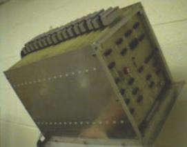
Figure 2‑2: A 163 resolution prototype of Cube-1 architecture
Cube-2 [7] implemented a 163 VLSI version of Cube-1 (Figure 2‑3). A single chip contained all the memory and processing of a whole Cube-1 board.
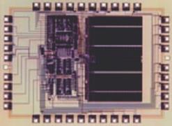
Figure 2‑3: A 163 resolution Cube-2 VLSI implementation
Although the prior Cube designs were fast, the foundations of volume sampling and rendering were not fully developed so the architecture was unable to provide higher order sampling and shading. Cube-3 [8] improved the quality of rendering by supporting full 3D interpolation of samples along a ray, accurate gray-level gradient estimation, and flexible volumetric shading and provided real-time rendering of 5123 volumes.
Due to the capability of providing real-time rendering, the cost and size of the Cube-3 was unreasonable. This prompted the development of Cube-4 [9] which avoided all global communication, except at the pixel level and achieved rendering in 1283 datasets in 0.65 seconds at 0.96 MHz processing frequency. There is also a new version Cube-4L which is currently being implemented by Japan Radio Co. as part of a real-time 3D ultrasound scanner [6, 10].
EM-Cube is a commercial version of the high-performance Cube-4 volume rendering architecture that was originally developed at the State University of New York at Stony Brook, and is implemented as a PCI card for Windows NT computers. EM-Cube is a parallel projection engine with multiple rendering pipelines. Eight pipelines operating in parallel can process 8 x 66 x 106 or approximately 533 million samples per second. This is sufficient to render 2563 volumes at 30 frames per second [6]. It does not support perspective projections.
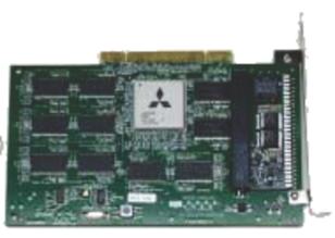
Figure 2‑4: The VolumePro PCI card
VolumePro [11], the first single chip rendering system is developed at SUNY Stony Brook and is based on the Cube-4 volume rendering architecture. VolumePro is the commercial implementation of EM-Cube, and it makes several important enhancements to its architecture and design. VolumePro is now available on a low cost PCI board delivering the best price/performance ratio of any available volume rendering system (Figure 2‑4).
Volume rendering techniques allows us to fully reveal the internal structure of 3D data, including amorphous and semi-transparent features. It encompasses an array of techniques for displaying images directly from 3D data; thus, it has become a key technology in the visualization of scientific volumetric data. Yet, when real time visualization is considered, it is obvious that, without the assistance of a specific hardware, this task cannot be achieved. In the following chapters, a solution to this problem will be examined which makes use of Digital Signal Processors.